
OK...maybe I'm just getting old but I look at the following:
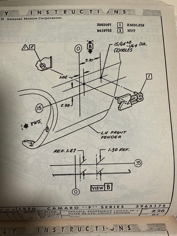
And all I can clearly reference is the body break line for vertical placement. What the heck is View B showing me?? I've tried to square this with Steve's (really awesome) reference:
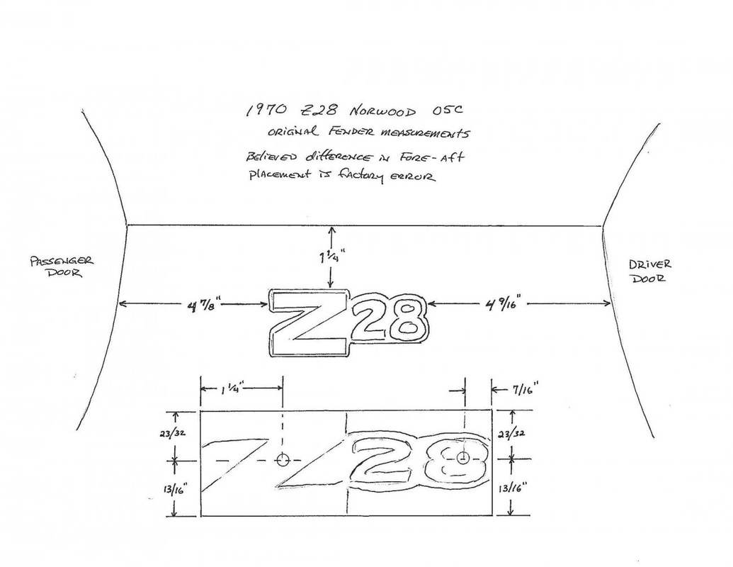
and I just can't make it work out (even allowing for "flexible" interpretation of the AIM on the assembly line).
I know I'm going to smack myself in the head when someone explains this to me like a five year old...but until then I'm just not seeing it.
And all I can clearly reference is the body break line for vertical placement. What the heck is View B showing me?? I've tried to square this with Steve's (really awesome) reference:
and I just can't make it work out (even allowing for "flexible" interpretation of the AIM on the assembly line).
I know I'm going to smack myself in the head when someone explains this to me like a five year old...but until then I'm just not seeing it.